Download
PDF Here
 |
Tools
Required:
- 12mm,
14mm, and 30mm sockets
- Adjustable
wrench
- Ratchet
and Breaker Bar
- Regular
Hammer
- 3/16
Diameter Pin Punch
- Snap
Ring Pliers
- 6mm
Allen Wrench
- Gasket
Scraper and/or Cleaner
- Access
to a Press
- Flat
Blade Screwdriver
- Ultra
Gray Silicon Permatex #599512
- Bearing
Grease or Assembly Lube
Guide
Sections:
|
|  21
and 23 Spline 21
and 23 Spline
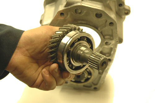
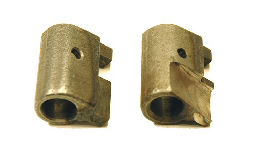
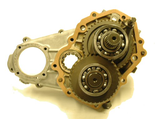
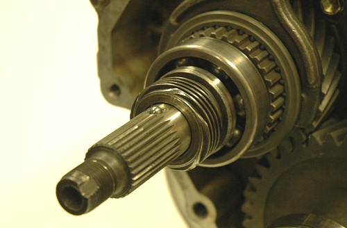
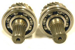
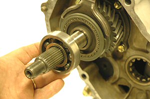
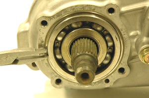
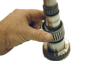
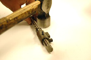
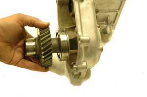
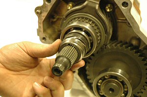
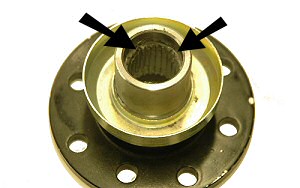
The
photo to the right shows 21 (left) and 23
(right) spline inputs side by side. Carb and
EFI 4cyl Pickup and 4Runners have transmissions
with a 21 splne output. V6 and Turbo trucks
have transmissions with 23 spline outputs.
Both input and output must be the same spline
count. For a single transfer case setup choose
the gear set that matches the spline count
of the transmission you are using. For dual
transfer case setup we recommend using stock
2.28 gears in front and 23 spline 4.70 gears
in the rear case.
Why
mix 21 and 23 spline in the same dual case
on 4cyl trucks?
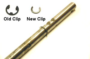
 All
4cyl Toyota trucks have the 21 spline output,
except for the Turbo 5sp trucks. Many people
run dual transfer case setups with 21 spline
inputs in both units of a dual transfer case
without problems. An even stronger setup is
to put a 23 spline gear set in the rear of
a dual transfer case. As the motor power comes
out of the transmission, the torque is more
than doubled when it goes through the first
reduction unit of a dual transfer case. This
means that torque going to the rear input
of a dual transfer case is about double that
of the front. If you purchase your gears and
dual adapter at the same time, get the 23
spline dual adapter and 23 spline gear set.
Using 23 spline components in the rear of
a dual case setup is stronger yet costs the
same as 21 spline components. If you use a
23 spline gear set in the rear, you must have
a dual adapter with a 23 spline coupler. If
you purchased a 21 spline dual adapter, you
can replace the coupler in order to use it
with 23 spline gears. All
4cyl Toyota trucks have the 21 spline output,
except for the Turbo 5sp trucks. Many people
run dual transfer case setups with 21 spline
inputs in both units of a dual transfer case
without problems. An even stronger setup is
to put a 23 spline gear set in the rear of
a dual transfer case. As the motor power comes
out of the transmission, the torque is more
than doubled when it goes through the first
reduction unit of a dual transfer case. This
means that torque going to the rear input
of a dual transfer case is about double that
of the front. If you purchase your gears and
dual adapter at the same time, get the 23
spline dual adapter and 23 spline gear set.
Using 23 spline components in the rear of
a dual case setup is stronger yet costs the
same as 21 spline components. If you use a
23 spline gear set in the rear, you must have
a dual adapter with a 23 spline coupler. If
you purchased a 21 spline dual adapter, you
can replace the coupler in order to use it
with 23 spline gears.
|
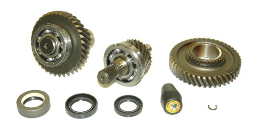
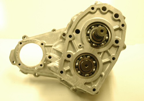
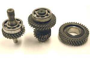
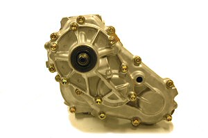
| Section
1: Parts List and Overview
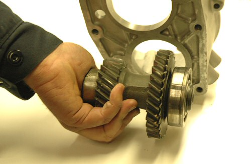
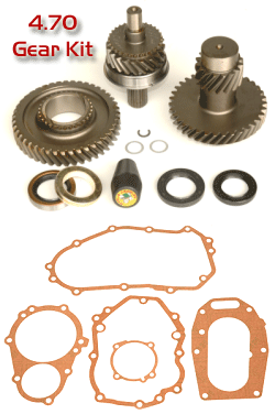
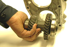
4.70
Gear Kit Parts List
21
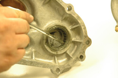
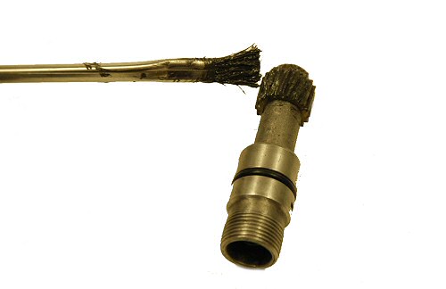
or 23 Spline input gear w/bearing
Low range gear
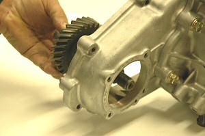
Counter shaft gear w/bearing
Transmission output seal
Rear output seal
Front output seal w/felt and retainer
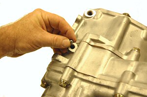
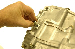
Shift fork clip
Drain and fill plug gaskets (2)
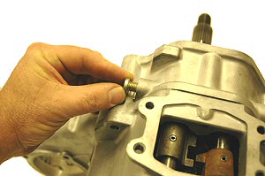
Complete
gasket set (5 pieces)
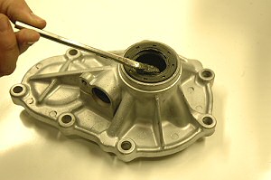
Marlin Crawler shift knob
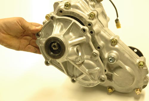
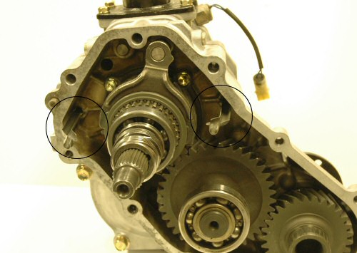
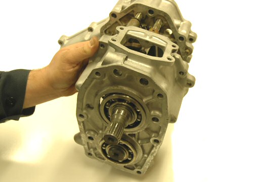
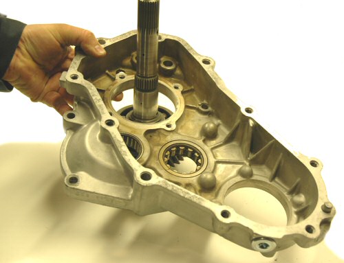
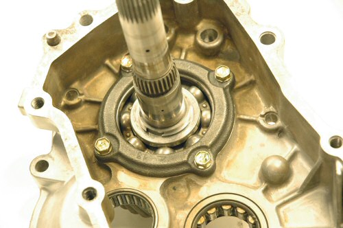
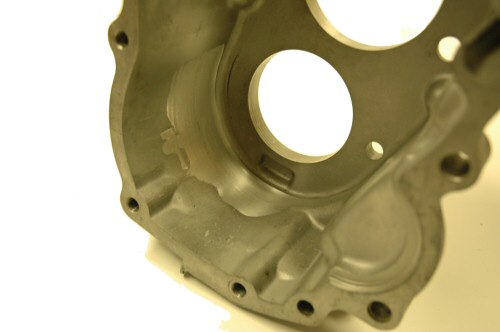
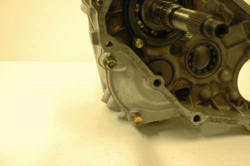
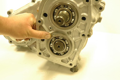
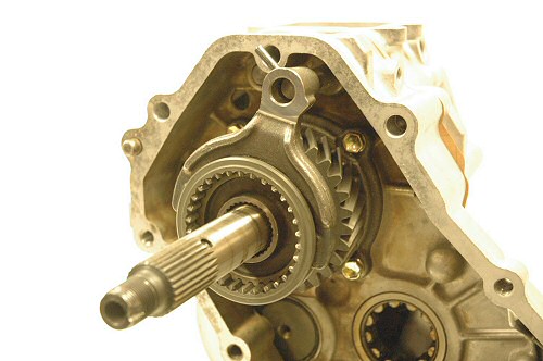
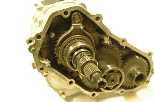
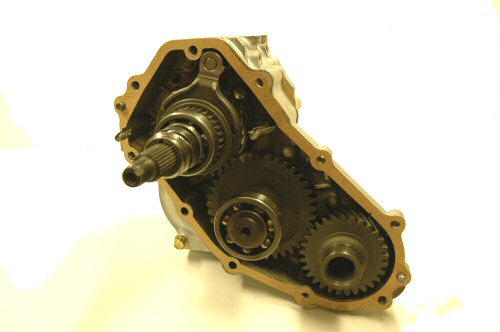
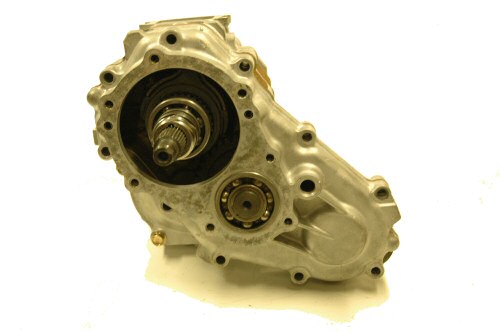
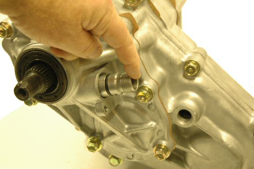
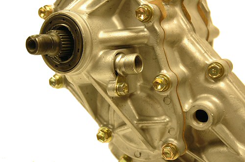
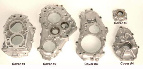
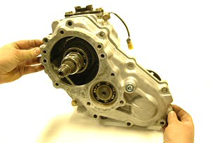
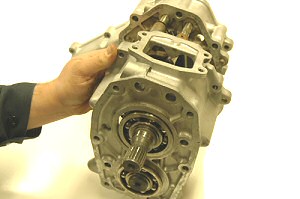
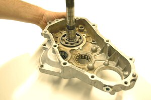
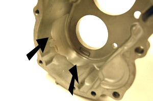
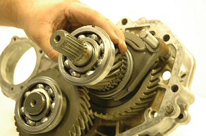
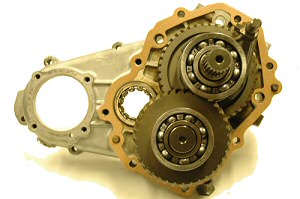
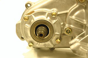
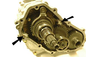
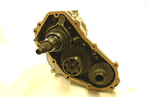
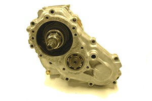
During
disassembly and reassembly we refer to different
transfer case housing sections by number.
The photo below shows each of the covers and
its number.
|
Section
2: Disassembly of Transfer Case
As
you take apart your transfer case we recommend you
label each part as it is removed.
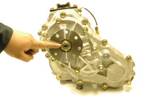
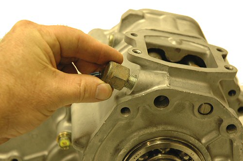
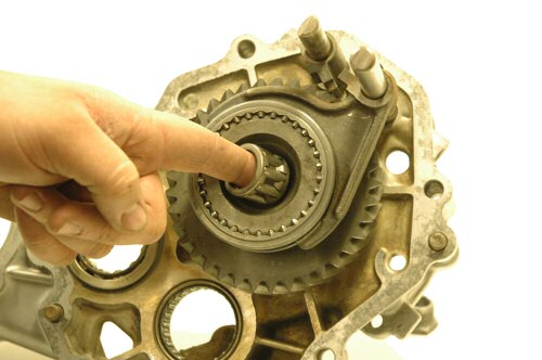
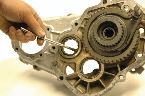
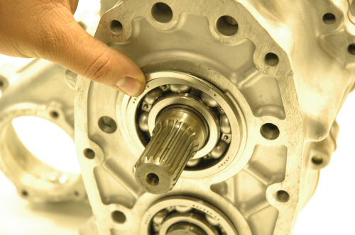
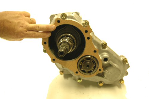
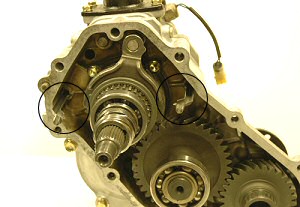
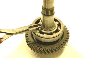
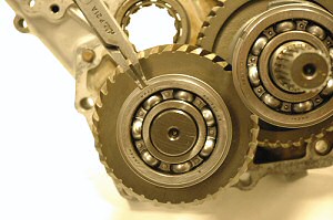
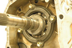
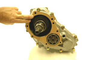
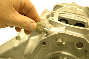
Step 1: Remove
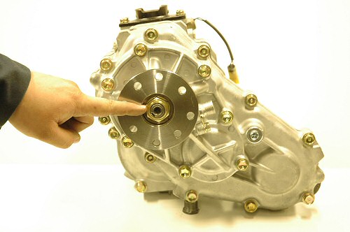
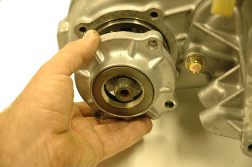
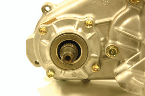
30mm rear nut and flange. |
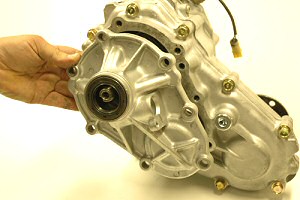
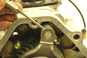
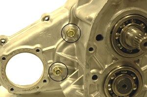
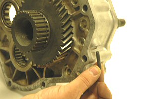
Step 2: Remove 7 bolts
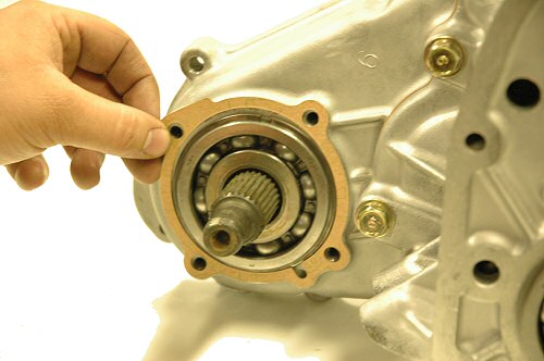
and cover #4. |
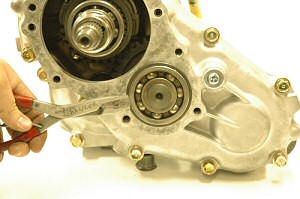
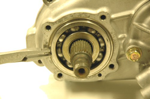
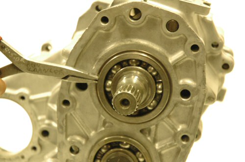
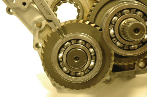
Step 3: Remove 4wd idler
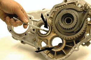
shaft bearing outer snap ring. |
Step 4: Remove 10 bolts
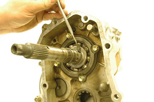
and cover #3. |
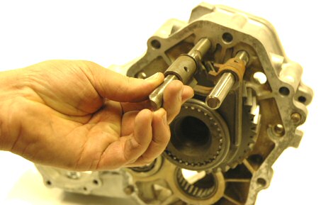
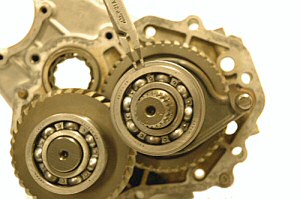
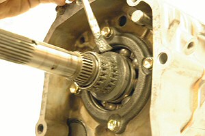
Step 5: Pull out and remove 2 oil transfer
tubes. |
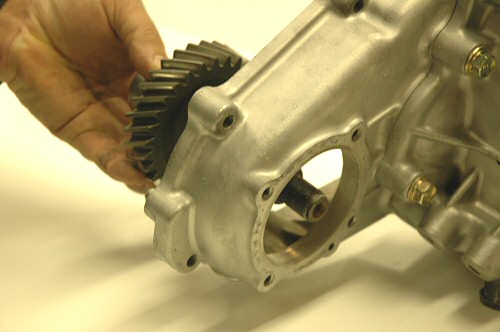
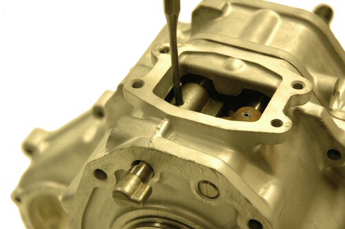
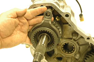
Step 6: Remove front drive idler gear.
|
Step 7: Remove speedo drive gear, lock
ball and oil pump gear. Do not loose ball!
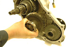
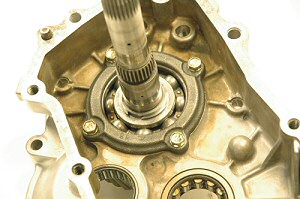
|
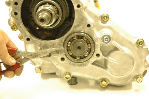
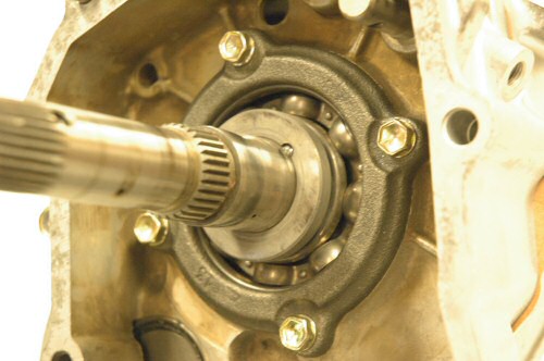
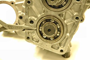
Step 8: Remove 63/28N rear main shaft
bearing. |
Step 9: Shift into 2wd high. Remove
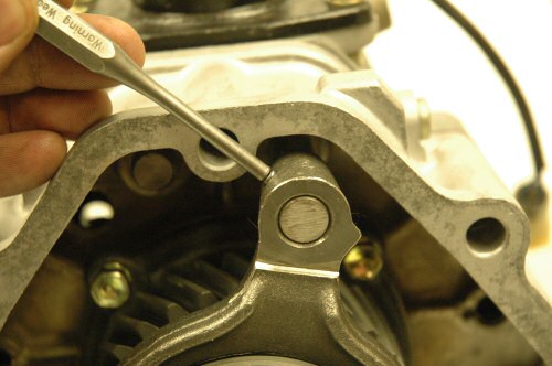
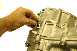
2wd/4wd shift fork roll pin with 3/16"
pin punch. |
Step 10: Remove 2wd/4wd shift fork and
shift collar. |
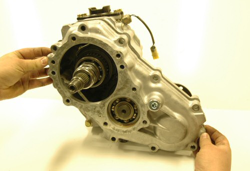
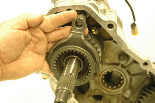
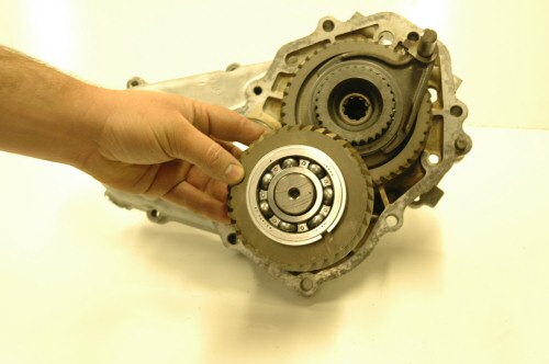
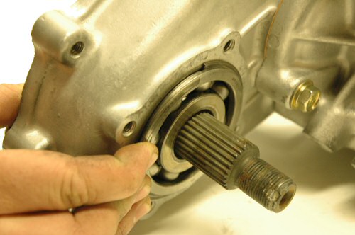
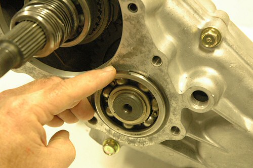
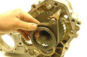
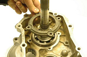
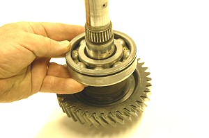
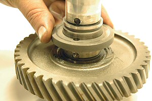
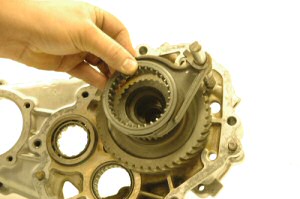
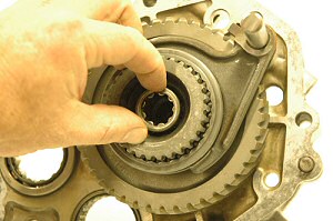
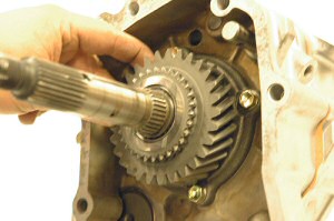
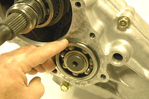
Step 11: Remove front output hub.
|
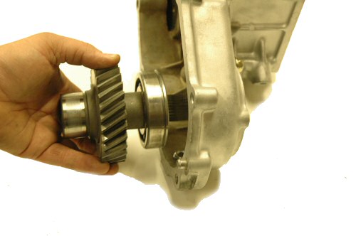
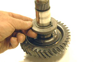
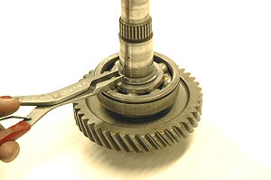
Step 12: Remove front output gear.
|
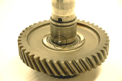
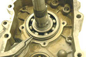
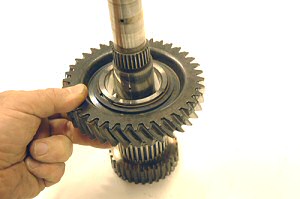
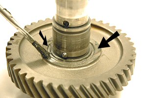
Step 13: Remove (2) 4wd
output gear cage bearings. |
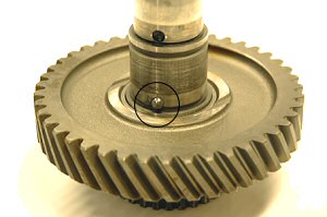
Step 14: Remove thrust
washer and it's lock ball. |
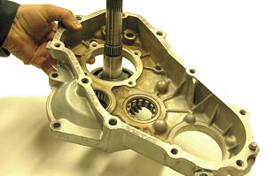
Step 15: Remove front
output 30mm nut and flange. Remove 4 bolts.
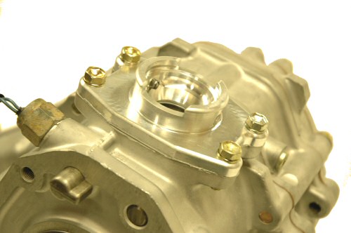
Remove cover #5. |
Step 16: Remove front
output snap ring. |
Step 17: Remove front drive output gear.
|
Step 18: Remove 4 bolts,
remove shifter base (top shift) or block off-plate
(forward shift) depending on model. |
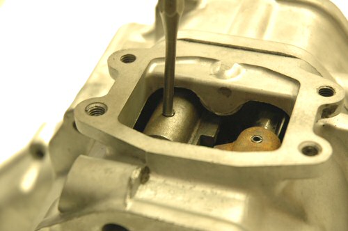
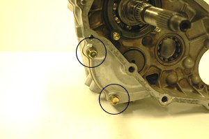
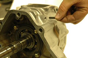
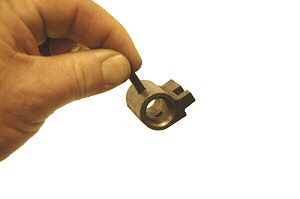
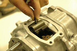
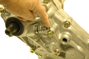
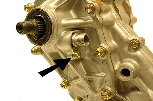
Step 19: Remove 4wd light switch (19mm
1989-1995 or 22mm 1979-1983) |
Step 20: Remove detent plug, ball and
spring from both sides of upper case. Rotate
case on side, then spring and ball will fall
out. |
Step 21: Remove remaining 4 bolts holding
cover #1. Two bolts are located on the front
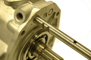
side, two are on the rear side. |
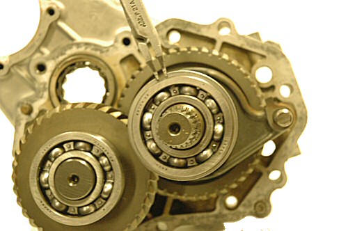
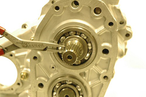
Step 22: Remove idler shaft bearing
snap ring. |
Step 23: Remove input shaft bearing
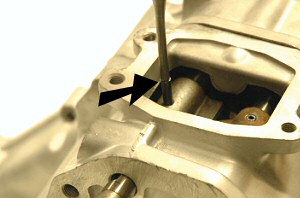
snap ring. |

Step 24: Drive out roll
pins from both shift rails. Pins will fall to
bottom of case. |
Step 25: Slide cover #1 forward and remove.
Retrieve two shift fork roll pins from bottom
of housing. |
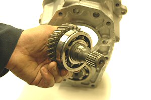
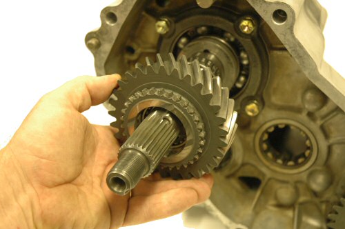
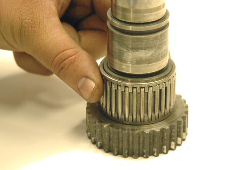
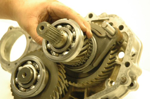
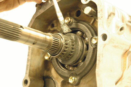
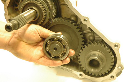
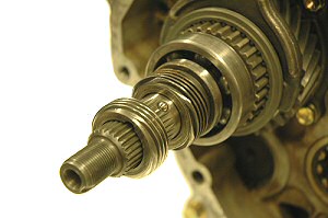
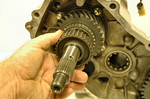
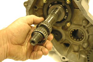
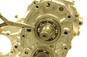
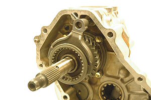
Step 26: Remove input gear. |
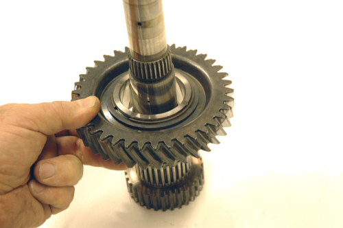
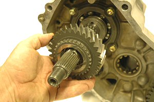
Step 27: Remove counter shaft gear.
|

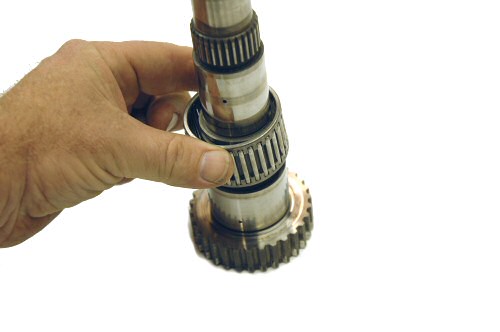
Step 28: Remove pocket bearing from main
shaft. |

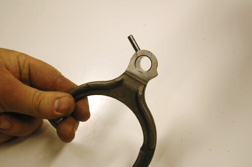
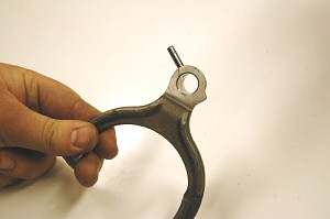
Step 29: Remove 2wd/4wd shift fork.
|
Step 30: Remove hi/lo shift fork and
shift collar. |
Step 31: Rotate case 90 degrees right,
tap case lightly to remove shift fork interlock
pin. |
Step 32: Remove 4 bolts and main shaft
bearing cover. |
Step 33: Remove main shaft bearing snap
ring. |
Step 34: Slide cover #2 off of main shaft.
|
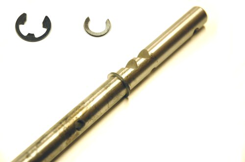
Step 35: Remove snap ring from main shaft.
|
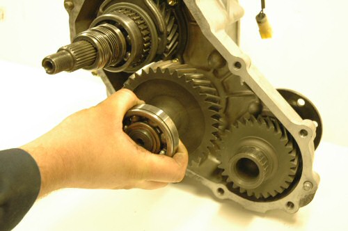
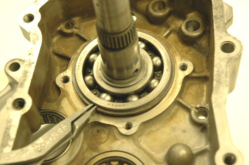
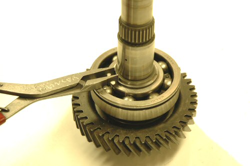
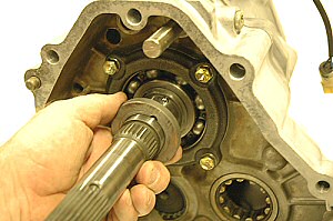
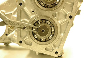
Step 36: Remove 6208N main shaft bearing
using press or gear puller. |
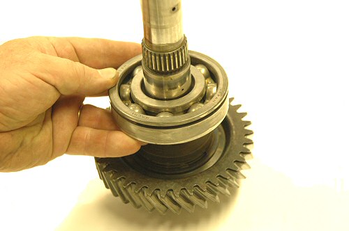
Step 37: Remove thrush washer and lock
ball. |
Step 38: Remove low speed gear from
main shaft. |
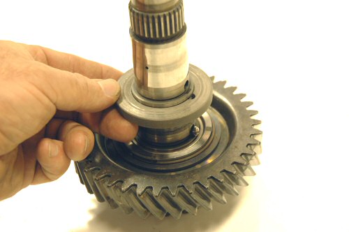
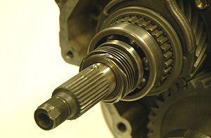
Step 39: Remove main shaft cage bearing.
|
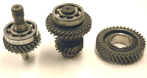
Step 40: Remove snap rings from input
and counter shaft gears above. The remaining
parts will not be used during reassembly.
|
| |
| Section
3: Reassembly of Transfer Case |
| 
Step 41: Apply grease
main shaft race way. Install low speed cage
bearing.
|
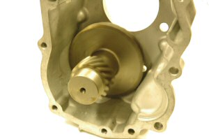
Step 42: Install new 4.70 low speed
gear onto main shaft.
|
| 
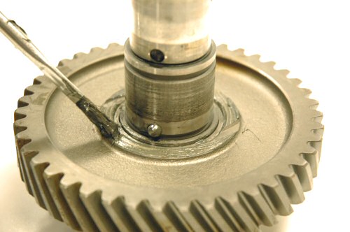
Step 43: Apply grease to the ball hole
and insert ball.
|
Step 44: Apply grease to face of
low speed gear as shown above.
|
Step 45: Slide thrust washer over main
shaft until seated onto face of low speed gear.
Line up notch in washer with ball. |
Step 46: Slide 6308N bearing
onto main shaft. Press bearing until it contacts
thrust washer. Install snap ring onto shaft.
|
Step 47: Slide cover #2 onto main shaft.
|
Step 48: Install bearing retainer
and 4 bolts. Torque to 10 ft/lbs. |
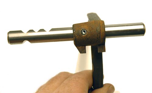
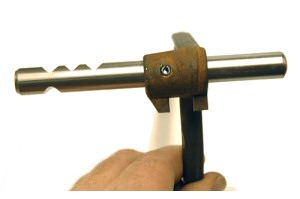
Step 49: Using a grinder or file,
remove inside radius on shift forks(s).
|
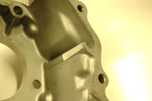
Step 50: Top shift
case only. Using a grinder, clearance shift
block as shown above. |
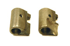
Step 51: On 79-83 models
only, replace C-Clip on 2wd/4wd shift fork with
new clip provided in kit. Clip is not used on
newer cases |
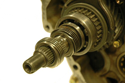
Step 52: Insert roll pin into low
range shift fork. Shaft can go in two ways,
install as shown above. |
Step 53: Install shift
rod, high/low fork and clutch sleeve.
|
Step 54: Grease pocket
bearing inside and out. Insert bearing into
main shaft. |
Step 55: Grease both idler and counter
shaft bearings as shown. |
Step 56: Using end
mill or hand grinder clearance case as required
to accept new 4.70 counter shaft. |
Step 57: Place counter shaft and
bearing in clearanced housing. Rotate counter
shaft to check for proper clearance. Gear should
not contact housing when spun. |
Step 58: Remove counter shaft from
cover #1 number and install into cover #2 as
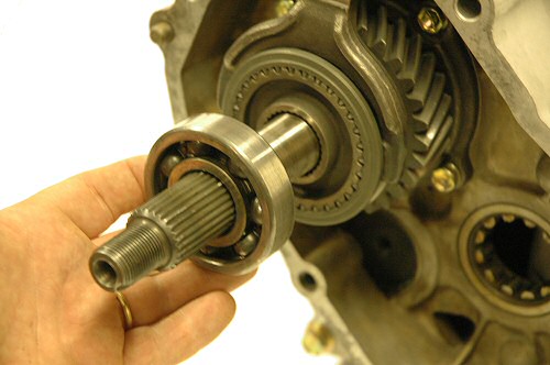
shown above. |
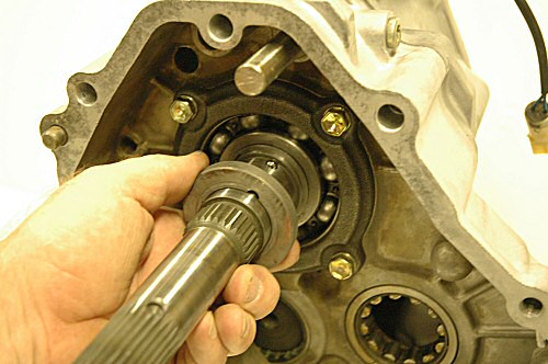
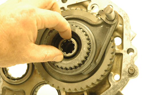
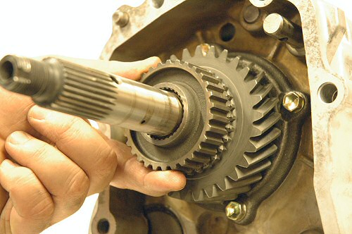
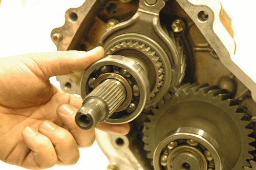
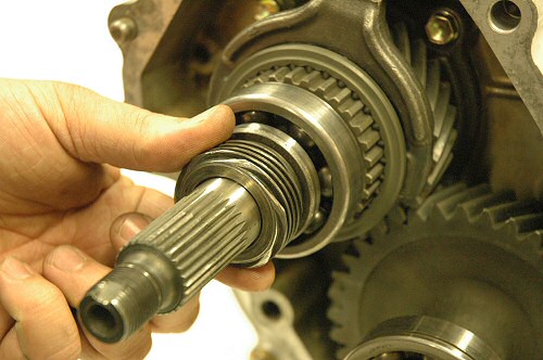
Step 59: Install input gear in main
shaft pocket bearing. |
Step 60: Remove snap
ring from counter shaft bearing. |
Step 61: Also remove
snap ring from input gear bearing. |
Step 62: Sometimes
it is necessary to clearance cover #1 near the
input gear as shown. Test fit to see if this
is necessary. Clearance up to 1/8" as needed.
|
Step 63: 79-83 cases
only. Install roll pin into shift block. Note
position of shift block fingers and shift rod.
Assemble as shown above. |
Step 64: Place new gasket onto cover
#2. |
Step 65: Slide cover #1 onto cover
#2. Carefully tap cover #1 with hammer until
cover #1 seats on cover #2. |
Step 66: Loosely install two bolts
on front of cover #1. Do not tighten yet.
|
Step 67: Loosely install
two bolts on back of cover #1. Do not tighten
yet. |

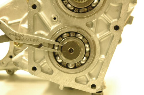
Step 68: Install snap ring onto input
gear bearing. |

Step 69: Install snap
ring onto counter shaft bearing. |

Step 70: Install inner
snap ring onto input gear bearing. |
Step 71: Install inner
snap ring onto countershaft gear bearing. Push
shift rod forward. |
Step 72: Insert interlock pin into
either detent spring hole. (Skip this step if
installing a twin stick) Turn the case on it's
side and tap if needed to get pin into place.
|
Step 73: Make sure
the interlock pin is all the way into position.
Here is can be seen and is not yet in position.
Push the pin in until it can no longer be seen.
|
Step 74: On 85-88 EFI models only,
place pin just far enough into shift block so
that you can pick up the block. |
Step 75: Use the pin to place shift
block into transfer case. Slide shift rail into
shift block. |
Step 75 (continued): Note position of detent
notches on 2wd/4wd shift rail. |
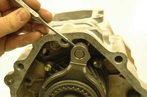
Step 77: Using a pin punch, drive
pin into place. |
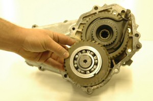
Step 78: Slide front
output gear with bearing into cover #2.
|
Step 79: Install snap ring around
the outside of the front output gear bearing.
|
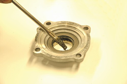
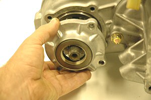
Step 80: Light press front output seal
felt and retainer into cover #5. |
Step 81: Turn over cover #5 and grease
inside of rubber seal surface. |

Step 82: Place this gasket onto face
of cover #2. |
Step 83: Install cover #5 using 4
bolts. Torque to 10 ft/lbs. |

Step 84: Apply grease to ball hole
on main shaft and place ball in hole.
|
Step 85: Slide thrust washer onto
main shaft and over ball. Apply grease to face
of thrush washer. |
Step 86: Apply grease to inside and
outside of both both front drive cage bearings.
Slide bearings onto main shaft. |
Step 87: Install front transfer drive
gear onto main shaft. |

Step 88: Apply grease to face of
front transfer drive gear. |

Step 89: Slide clutch hub onto main
shaft. |
Step 90: Push roll pin into hi/lo
shift fork just far enough so it will not fall
out. |
Step 91: Install clutch sleeve and
shift fork onto 2wd/4wd shift rail. |
Step 92: Using a 3/16" pin punch,
drive roll pin into shift fork so that it is
flush with the fork. |

Step 93: Install original front drive
idler gear. |

Step 94: Install output shaft rear
bearing. |

Step 95: Slide oil pump drive gear
onto main shaft as shown. |
Step 96: Apply grease to ball hole
and place ball into hole. |
Step 97: Slide speedo drive gear
onto main shaft. |
Step 98: Install oil transfer tubes
as shown. |
Step 99: Place new gasket onto rear
of cover #2. |
Step 100: Apply grease to cage bearing
in rear of cover #3. |
Step 101: Install cover #3 onto the
back of cover #2. Be careful to align oil transfer
tubes in the cover. Install 10 bolts into cover
#3. Torque to 29 ft/lbs. |
Step 102: Install snap ring onto
idler bearing. |
Step 103: Place new gasket onto back
of cover #3. |
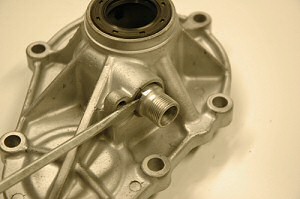
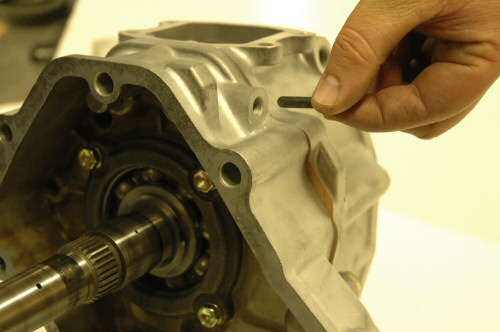
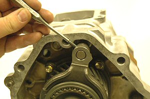
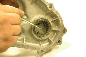
Step 104: Remove speedo lock bolts
and tab. Using a screwdriver remove the speedo
drive gear from cover #4. |
Step 105: Remove old seal and install
new seal into cover #4. |
Step 106: Install cover #4 onto the
back of cover #3. Install 7 bolts into cover
#4. Torque to 29 ft/lbs. |

Step 107: Apply grease to speedo
drive gear. |
Step 108: Slide speedo drive gear
into cover #4. |
Step 109: Install speedo gear lock
bolt and tab, torque to 10 ft/lbs. |
Step 110: With the case on it's side,
drop in one detent ball. |
Step 111: Now drop in a detent spring
after the ball. |
Step 112: Apply silicon to the threads
of the detent plug and install. Flip the case
over onto the other side and install the ball,
spring and plug the same way. |
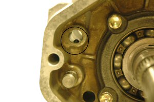
Step 113: Install 4wd shift light
switch into cover #1. |
Step 114: Apply silicone to the spines
inside both flanges. |
Step 115: Install flange. Note, the
silicone will bulge out just a bit. You should
see a slight bulge on each of the splines.
|
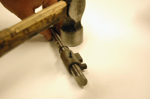
Step 116: Install the main shaft
nuts and tighten to 90 ft/lbs. Using punch,
drive the stake nut into the main shaft as shown
above. Repeat for rear flange. |
| Step
117: Tighten 4 bolts on cover #1 that
were left loose in step #66 & 67. Torque
to 29 ft/lbs. Replace drain and fill plug
washers with ones provided. Install transfer
case into truck. Using the rear fill plug,
fill transfer case with 80/90W GL5 gear oil.
Do not over fill. No brake in is required
for 4.70 gears, we do recommend replacing
the oil after the first 1,000 miles and every
30,000 miles thereafter. Conventional or synthetic
oil may be used.
Torque Specs:
8 X 1.25mm
bolts with 12mm head 10 ft/lbs
10 X 1.25 mm bolts with 14mm head 29 ft/lbs
30mm front and rear flange nuts 90
ft/lbs
|
|